Consistent structural analysis of HDD pipes in accordance with DWA-A 161 / DVGW GW 312
Horizontal directional drilling (HDD) is a proven method for laying pipes without trenching. Pipes for water supply and disposal, gas, electricity and telecommunications pass under roads, railway lines, rivers and existing infrastructure. The intervention is usually limited to the start and end pits, while traffic continues to flow undisturbed.
Specialists are consulted for the execution of HDD measures. This article examines all structural aspects for the installation and operation of the pipes as part of the planning and offers a comprehensive, self-contained design concept.
During its service life, the pipeline should be stable. To achieve this, it must be able to absorb and transfer earth loads, groundwater, internal pressure or traffic loads around its circumference at all times without exceeding permissible stresses, expansions or deformations. During the construction phase and subsequent operation, a number of special features must be taken into account.
Construction state
Figure 1 shows the principle of horizontal directional drilling based on DWA-A 125 Figure 15 [source 3].
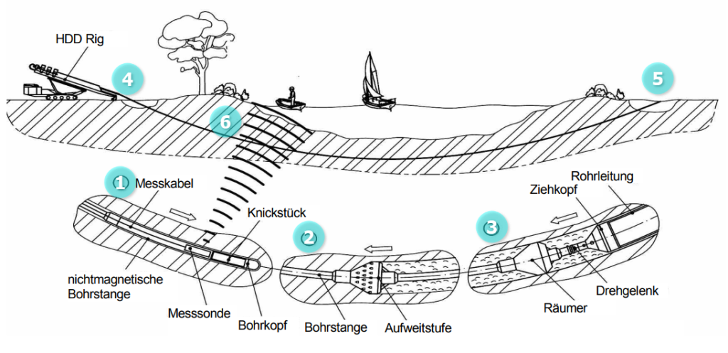
The following steps are required for horizontal directional drilling:
1) Drilling the pilot pipe from the starting pit (rig side (4)) to the target pit (pipe side (5)); working direction: from (4) to (5)
2) Expanding the borehole in one or more stages (reaming)
3) Pipeline Pullback; working direction: from (5) to (4)
Routing, selection of the drill rods, soil expertise and support of the borehole by means of suitable suspension adapted to the soil are planning tasks in the construction phase. The required pulling force for the machine design can be determined according to the DCA guideline [source 2].
Pull in: Normal force longitudinal
Point (4) in Figure 1 is decisive for the pipe: The maximum tensile force is applied at this point, as the pipe lies completely in the bore hole and is therefore subjected to casing friction over the entire length of the drill hole. The tensile force is distributed evenly over the pipe wall, which forms a circular ring in cross-section (axial surface). Each fibre of this ring is under tensile stress, shown graphically in Figure 2.
The pulling force of the machine generates tensile stresses in the pipe wall that are perpendicular (normal) to the surface under consideration. In statics, this force acting on the cross-section is therefore referred to as normal force N. If the normal force generates tensile stresses, its sign is positive, N > 0; if compressive stresses result, the following applies: N < 0. In Figure 2, the colour blue was selected for the positive stresses (tensile). All fibres are pulled, the cross-section is 100% under tension. In contrast to bending – see the following section – where only the outermost fibre experiences the maximum stress, there are no reserves.
Curvature: longitudinal bending moment
The most unfavourable point along the route is where the pipe experiences the smallest bending radius in the longitudinal direction. Point (6) in Figure 1 serves as an example here. This results in the largest curvature as a reciprocal value and the pipe wall is stretched or compressed to the maximum, which results in the decisive bending moment M and the maximum bending stresses. The cross-section is subjected to 50% tensile and 50% compressive stresses.
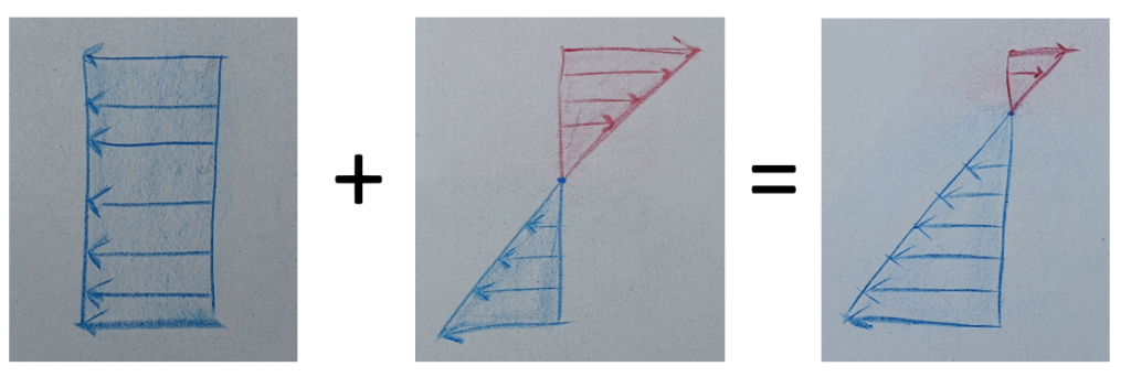
Figure 3 shows: Tensile stresses, positive, in blue; and compressive stresses, negative, in red. The stresses are zero in the pipe axis, where the neutral fibre of the cross-section is located. The external fibres are decisive for the design; reserves can be activated by relocation.
Longitudinal superposition
For the longitudinal dimensioning, the utility pipe must be verified with regard to
a) Existing tensile stress < absorbable tensile stress
b) Existing bending stress (tension or compression) < absorbable bending stress (tension or compression)
c) Interaction of tension with bending
This relationship is illustrated graphically in Figure 4: The compacted or compressed zone becomes smaller, while the pulled or stretched area grows. The neutral fibre moves towards the inside of the bend, i.e. upwards in the case of the pipe in the borehole. While the (negative) compressive stress from the bending and the (positive) normal force from the pulling-in subtract in the pipe crown, the tensile stresses in the bottom of the pipe add up.
Absorbable tensile and bending stresses are listed as material-dependent parameters, for example in worksheet DWA-A 127-10 [source 4]. The design of the longitudinal direction in the operational state is complete when the verifications for tension, bending and their interaction have been provided.
Buckling pressure in circumferential direction
The pilot hole is usually accompanied by a drilling fluid, the pressure and composition of which depends on the soil properties and groundwater level, among other things. After widening and during the pulling-in process, the borehole is supported by a suspension. From a static point of view, this support and lubricant acts on the pipe from the outside as fluid pressure in the circumferential direction and generates negative normal stresses, pure pressure. This creates the risk of abrupt failure due to so-called buckling, and proof of stability must be provided.
Once installation is complete, the media or product pipe enters the operating state.
Operational state
During use, the pipe is subjected to the impacts mentioned at the beginning mainly via its circumference, which is why the longitudinal direction can generally be ignored for the verification of the operating condition.
Longitudinal bending in the operational state?
For the sake of completeness, it should be mentioned:
- The longitudinal curvature or bending of the construction state is retained in the final state.
- The effects are weakened by material-specific behaviour such as creep, shrinkage or relaxation.
- It is up to the installer to decide whether a superposition of longitudinal and circumferential direction is necessary or useful. For this purpose, it would have to be considered on a project-specific basis whether and at what point the relevant influences from the longitudinal and circumferential directions actually coincide locally.
- Experience has shown that trenchless pipelines are subject to higher loads during the construction phase.
Fatigue verification
If the pipeline crosses under traffic routes and is therefore regularly passed over by vehicles, railways or aeroplanes, the DWA regulations require verification against non-predominantly static loads, often referred to as dynamic proof or fatigue verification, for the service life usually estimated at 50 years. This involves comparing the permissible stress double amplitude for a certain number of load cycles with the effects of traffic loads. In road traffic, the number of load cycles is 2×10\^6, for railway traffic load 1×10\^8.
Material-specific particularities
The pipes must be able to transfer longitudinal forces to be pulled into the borehole. Various methods have been established for this purpose. Materials are:
- Steel as a homogeneous and isotropic material, independent of time, continuous wall thickness. The tensile force that can be absorbed results from the ring area and the permissible stress of the material.
- Time-dependent materials: plastics such as PE, PVC, PP
- Tensile forces, bending radii and bendability are listed in the appendices of worksheets DWA-A 161 / DVGW GW 312 and DVGW GW 321 [source 6]. The permissible tensile forces apply for a temperature of 20°C and up to 30 minutes of exposure. Reductions must be applied for higher or lower pipe wall temperatures. Pull-in duration and, if present, additional bending stress must be taken into account.
- Example for a DN/OD 200 pipe made of PE100, SDR 17: Permissible tensile force N
- 20°C, up to 30′: N = 70kN (exact calculated value)
- 20°C, up to 30′: N = 67kN (table value)
- 40°C, up to 30′: N = 47kN (table value)
- 20°C, greater than 30′: N = ~60kN (10% reduction)
- 40°C, greater than 30′: N = ~42kN (10% reduction)
- In the unfavourable case of increased outside temperature and longer pull-in time, N = 42kN instead of N = 67kN (approx. 63%).
- Pipes made of steel or plastic are usually laid out and welded as a complete strand on the pipe side before pulling in.
- Cast iron, BLS socket: Instead of the tensile force determined via the axial surface and permissible stress of the material, the manufacturer-specific socket connection is decisive. For a DN600, the force that can be transmitted through the socket is approx. 1.5MN compared to the wall with around 8MN.
Dimensioning with the help of a software solution
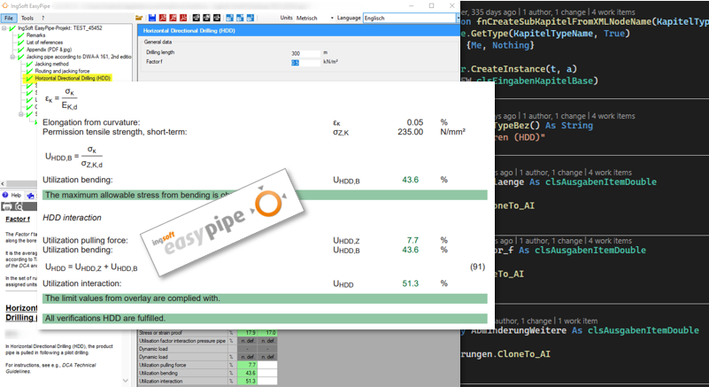
The multilingual IngSoft EasyPipe calculation programme (Figure 5) has enabled the structural calculation of underground pipes and shafts since 1997. Since February 2024, the calculation module for DWA-A 161 / DVGW GW 312 for jacking pipes can be used self-contained to verify HDD methods.
All required parameters are queried via the graphical user interface. In addition to all verifications, the verifiable printout contains information on the minimum bending radii.
Conclusion
As a rule, pipelines installed using the HDD method must be dimensioned for the construction and operating condition and analysed in both the longitudinal and circumferential directions. The actions are compared with the strengths. The following findings should be emphasised:
- The longer the route or the greater the bore length and/or diameter, the higher the calculated tensile force required.
- The smaller the radius of curvature in the route (not in a possible upper bend), the higher the bending stresses in the longitudinal direction.
- The decisive factor is usually the state of construction.
- A pipe statics programme is available on the market that supports the design engineer with a self-contained concept.
History
- 1990-01 Worksheet ATV-DVWK-A 161: Jacking pipes (global safety concept)
- 2010-09 Worksheet DWA-A 161 / DVGW GW 312: Draft, yellow print
- 2010 – 2013 Worksheet DWA-A 161 / DVGW GW 312: Comments on the draft
- 2014-03 Worksheet DWA-A 161 / DVGW GW 312: Publication, white print
- 2016 – 2021 Code of Practice DWA-A 161 / DVGW GW 312: Correction sheets, English translation, adaptation of verification concept against non-predominantly static loading for steel pipes; TM 4-2019 of DB NETZ AG; material characteristics according to DWA-A 127-10
- 2022-09 NO DIG Berlin: Lectures on trenchless methods for the regulations DWA-A 161 and DWA-A 143-2
- 2023-04 Vortriebsforum Nürnberg / 2023-05 ptc (Pipeline Technology Conference) Berlin: Live demonstration of axial buckling with a beverage can
- 2023-05 IngSoft EasyPipe v2.11: Calculation of the required tensile force according to DCA guideline; superposition of longitudinal stresses from tension and bending in the construction stage; BETA for HDD
- 2024-02 IngSoft EasyPipe v2.11.5.3 (current version): Finalisation of the calculation logic in the operational state, removal of the BETA stage
- 2024-03 NO DIG Berlin: Live demonstration of pull-in process
- 2024-05 Publication on the static calculation of HDD procedures (3R, Water Solutions)
Applicable documents, regulations, standards
Rules and regulations
1) Arbeitsblatt DWA-A 161 / DVGW GW 312: Statische Berechnung von Vortriebsrohren (2014-03 mit Korrekturen 2021-03) [Structural design of jacking pipes]
2) Technische Richtlinien des DCA (Drilling Contractors Association): Informationen und Empfehlungen für Planung, Bau und Dokumentation von HDD-Projekten, 4. Auflage 2015. Verband Güteschutz Horizontalbohren e.V. (DCA), Aachen – [DCA Technical Guidelines]
3) Arbeitsblatt DWA-A 125: Rohrvortrieb und verwandte Verfahren, Dezember 2008 [Pipe jacking and related methods]
4) Arbeitsblatt DWA-A 127-10: Statische Berechnung von Entwässerungsanlagen – Teil 10: Werkstoffkennwerte, September 2020 [Structural analysis of drainage systems – Part 10: Material properties]
5) Vortrag auf der NO DIG 2024, Berlin von Frederik Müller: Überlegungen eines Bauingenieurs zum strukturellen Aspekt von HDD-Installationen mit Kreide und Schnur [Reflections of a civil engineer on the structural aspect of HDD installations with chalk and cord]
6) DVGW-Arbeitsblatt GW 321: Steuerbare horizontale Spülbohrverfahren für Gas- und Wasserrohrleitungen – Anforderungen, Gütesicherung und Prüfung, Oktober 2003 [DVGW Code of Practice GW 321: Controllable horizontal flush drilling methods for gas and water pipelines – Requirements, quality assurance and testing]

ppa. Frederik Müller
Abteilungsleiter Statik, Prokurist Statik IngSoft GmbH